Hongshi MicroLED Optoelectronics Explained.
Each article starts with a simple question and explores one principle.
Place several MicroLED light engines of the same model side by side. All use RGB cube and display the same white image, yet the results may not look exactly alike. Even when the red, green and blue images are aligned, some areas may appear brighter than others, and the white may have a slight color cast.
These differences need to be measured and calibrated during production. In this article, we look at luminance uniformity and white-point calibration to understand how light engines achieve more consistent output.
First, Check the Alignment of the Three Color Images
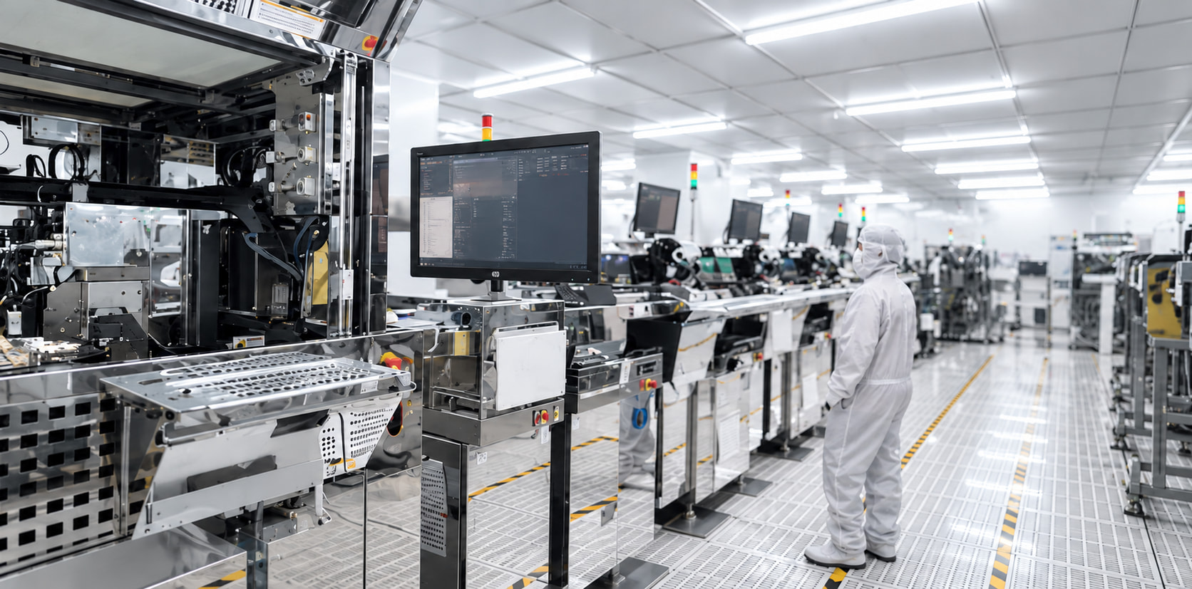
As explained in the second article, active alignment is used to make the red, green and blue images overlap within specified tolerances. Once the components are assembled and fixed in place, the actual output image must be checked. A unit that exceeds the alignment tolerance cannot be accepted for delivery.
This is the starting point for subsequent calibration. Luminance compensation and white-point calibration serve different purposes; neither can replace verification of the three images' alignment.
Making Brightness Uniform Across an Image
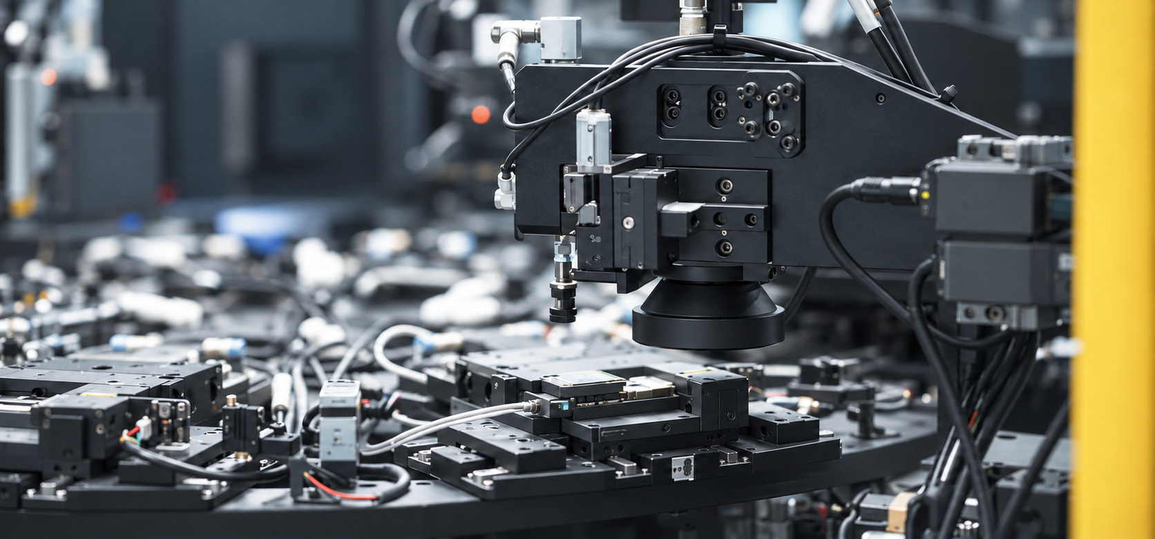
First, consider a single microdisplay panel. When it displays an image intended to have uniform luminance, the actual output may be brighter in some areas and dimmer in others. If these variations remain, the combined image may also appear uneven.
To address this, measurement equipment records luminance at different positions. Compensation parameters are calculated from the differences between the measured and target values, and the drive output at the corresponding positions is adjusted. This type of compensation for display non-uniformity is commonly known as Demura.
When calibrating a light engine that uses RGB three-color optical combining, we first address luminance uniformity in the red, green and blue panels separately. Compensation must be based on measured data, followed by another output check to confirm that the result meets the requirements.
Here, “uniformity” concerns brightness differences within a single image. Whether the overall luminance is consistent from one light engine to another is a separate question. That must be checked against the same specifications under the same test conditions.
Calibrating White to the Same Target
Once the luminance of each panel has been made more uniform, the next step is to adjust the white they produce when combined.
In the first article, we explained that red, green and blue light, combined in the right intensity ratios, are perceived as white. But applying the same drive settings to different light engines does not necessarily produce the same white. The actual optical output of each channel can still vary from unit to unit.
White-point calibration starts by measuring the chromaticity coordinates of the combined light. The relative output of the red, green and blue panels is then adjusted to bring the white point to the specified target. D65 is a commonly used white-point reference in the display industry, and we also use the D65 white point for this calibration. Whether a unit passes depends on whether its measured result falls within the specified tolerance.
The RGB drive ratios must also be determined from the actual optical output and measured chromaticity coordinates. One fixed ratio cannot replace measurement. After white-point calibration, luminance and uniformity must be checked again to confirm that all requirements are met simultaneously.
A common calibration target, therefore, does not mean every light engine should use identical settings. Each unit needs compensation and calibration based on its own measurements to keep adjustable differences within the specified limits.
The color combining, alignment and light collection discussed in the first three articles must ultimately be reflected in the image that a light engine actually produces. At Hongshi, inspection and calibration during volume production help ensure that these optical requirements are met in the products we deliver. When customers integrate the light engine with waveguides or other optical systems, the output of the complete device must also be checked and calibrated.